
Winch Drive: Types, Working & Industrial Applications
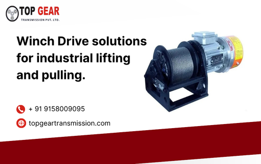
What Is a Winch and Why Does It Matter Industrially? A winch winds or unwinds a rope, cable, or chain around a drum to lift, lower, pull, or position heavy loads with controlled force. At its core, a winch drive is the complete powertrain assembly that integrates a motor, gearbox, drum, and braking system into a single functional unit capable of generating high pulling force across demanding industrial environments. In industrial contexts, the winch is far more than a simple cable-winding tool. It is a precision load-handling mechanism. It must perform reliably under extreme conditions, including high temperatures, corrosive marine environments, explosive atmospheres, and heavy-duty cycles. Industries ranging from deep-shaft mining to steel plants depend on these drives. They execute critical load movements that cranes or conveyors cannot perform. The global industrial winch market continues to expand as capital infrastructure projects in emerging economies demand greater material handling capability. Understanding how winch drives work, the different types available, and how to select the right configuration is essential for procurement engineers, plant designers, and maintenance managers. How Winch Drives Work Drum, Gearbox & Motor Integration A winch drive functions as an integrated power transmission system. The primary components are the prime mover (electric motor, hydraulic motor, or PTO shaft), a multi-stage reduction gearbox, a rope drum, and a failsafe braking system. The motor generates rotational torque, which the gearbox reduces in speed while amplifying in force before transferring it to the drum. The drum winds the steel wire rope or synthetic rope, exerting the required line pull on the connected load. The winch drive’s gearbox typically uses a planetary or helical gear arrangement. This design achieves very high reduction ratios within a compact housing. Engineers prefer planetary gear stages in heavy-duty winch drives. They distribute the load across multiple planet gears, which increases torque density and reduces bearing stress. Depending on line speed and pull requirements, gear ratios can range from 20:1 to over 500:1. Load Pulling Mechanism When the winch operates, the motor spins the gearbox input shaft. After multi-stage reduction, the gearbox output shaft rotates the drum at a controlled, lower speed. The rope wound on the drum unwinds (paying out) or winds (hauling in) to move the attached load.A spring-applied, hydraulically or electrically released disc or band brake automatically engages when the motor de-energizes, holding the load securely and preventing runaway during a power failure. The effective line pull of a winch decreases as more rope layers accumulate on the drum, since the larger effective drum radius reduces the mechanical advantage. Engineers therefore specify the first-layer line pull as the rated capacity, and account for multi-layer derating in the application design. Types of Industrial Winches Electric Winch An electric winch uses an AC or DC electric motor as the prime mover. It offers precise speed control (especially when paired with a variable frequency drive), clean operation, and straightforward integration with automation systems. Electric winch drives are best suited for applications where grid power is accessible and the environment is relatively clean. Common sectors include material handling, construction hoisting, steel plants, and theatre rigging. They are available in enclosure classes from IP55 to IP66 for outdoor and wash-down environments. Hydraulic Winch A hydraulic winch uses a hydraulic motor fed by a pump circuit as the prime mover. It delivers exceptionally high torque at very low speeds and can sustain continuous full-load duty cycles without overheating, making it the preferred choice for heavy offshore, marine, and mining applications. The hydraulic winch also offers inherently smooth, stepless speed control through hydraulic valve modulation, and is inherently compatible with ATEX hazardous area requirements since there are no electrical components at the point of actuation. Engineers widely specify hydraulic winches for offshore mooring systems, subsea construction vessels, drilling rigs, and anchor-handling tug supply (AHTS) vessels requiring continuous pulling forces over 100 tonnes. Mechanical / PTO Winch A mechanical or power take-off (PTO) winch draws power directly from a vehicle or machine engine via a PTO shaft and gearbox. It eliminates the need for a separate motor, and operators commonly fit it to all-terrain trucks, forestry equipment, recovery vehicles, and mobile cranes. Mechanical winch drives can include an idle gear reverse mechanism, allowing operators to change the drum direction without reversing the engine. Air / Pneumatic Winch A pneumatic winch uses compressed air to drive a vane or piston motor. It is the safest option in highly explosive or flammable environments where neither electrical nor hydraulic systems are practical. Pneumatic winch drives are used in chemical plants, petrochemical facilities, and underground coal mines. They are inherently speed-regulated by air pressure and offer natural overload protection. Key Technical Specifications Selecting the correct winch drive requires a thorough understanding of its technical parameters. Below are the critical specifications to evaluate: Parameter Specification Capacity (Line Pull) 2,500 N to 500,000 N Line Speed 0.1 m/min to 50 m/min Rope Length As per customer requirement Rope Diameter As per customer requirement Mounting Type Foot or side mounting Brake Type Failsafe brake (integrated or external) Motor Compatibility Electric, Hydraulic, Mechanical (PTO), Pneumatic IP Class (typical) IP55 to IP67 (application dependent) Gear Ratio High reduction in compact housing Line Pull Line pull is the rated pulling force, expressed in Newtons (N) or kilonewtons (kN), that a winch can exert on the rope at the first layer on the drum. Industrial winch drives are available from 2,500 N (approximately 0.25 tonnes) to 500,000 N (50 tonnes) and beyond for specialised marine applications. Rope Capacity Rope capacity refers to the total length of rope the drum can accommodate at a given diameter. For a given drum geometry, a smaller rope diameter allows a longer rope. Engineers specify rope diameter based on the minimum breaking load (MBL) requirement, with a standard safety factor of 5:1 for most industrial winch applications and 6:1 or higher for personnel-adjacent lifting. Gear Ratio The gear ratio determines the relationship between input speed (motor RPM) and output speed (drum RPM), and inversely affects the torque multiplication. A
Electric Winches: Types, Applications & Benefits
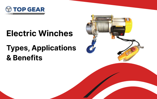
What Is an Electric Winch? An electric winch is a load-pulling device powered by an AC or DC electric motor, used to wind or unwind a wire rope or synthetic rope around a drum to lift, lower, or haul heavy loads. Electric winches are among the most widely deployed winch types across both industrial and off-road sectors due to their clean operation, precise speed control, and straightforward integration with electrical control systems. From construction hoists and crane mechanisms to off-road recovery vehicles, electric winches deliver controlled, repeatable load handling without the hydraulic plumbing or compressed-air infrastructure required by alternative winch types. 2How Electric Winches Work DC/AC Motor, Drum & Gearbox Assembly An electric winch integrates a DC or AC motor, a reduction gearbox, and a rope drum into a single assembly. The motor’s output shaft drives the gearbox input, which reduces speed and multiplies torque before turning the drum. As the drum rotates, it winds the rope to generate pulling force or pays out rope to lower or release the load. Most electric winches used in heavy-duty applications use planetary gear reduction for its compact size and high torque density. Control Systems (Remote, Pendant, Auto-Brake) Operators run modern electric winches via pendant control stations, wireless remote controls, or integrated control panels. These systems allow them to control direction and, in variable-speed units, the rate of rope travel. An automatic failsafe brake typically spring-applied and electrically released engages whenever the motor de-energizes. This action holds the load securely and prevents uncontrolled drum rotation during a power interruption. Types of Electric Winches Industrial Electric Winch Manufacturers design industrial electric winches for continuous or heavy intermittent duty. These systems utilize a robust planetary gearbox, feature IP55–IP66 rated enclosures, and offer capacities ranging from under one tonne to over fifty tonnes. Off-Road / Vehicle-Mounted Electric Winch Vehicle-mounted electric winches are fitted to trucks, four-wheel-drive vehicles, and recovery equipment for self-recovery and towing applications, drawing power from the vehicle’s battery and typically rated for intermittent duty cycles due to motor thermal limits. Marine Electric Winch Marine-grade electric winches are constructed with corrosion-resistant materials and sealed enclosures to withstand salt spray and humidity, used for anchor handling, mooring, and onboard load positioning on vessels. ATV / UTV Winch Compact electric winches designed for all-terrain and utility vehicles offer lower line pull ratings, typically under 5,000 lbs, suited to recreational and light recovery use. Key Specifications & Ratings Line Pull (lbs / tonnes) Line pull defines the maximum rated pulling force of an electric winch, expressed in pounds for off-road units or tonnes/Newtons for industrial units. This rating applies to the first rope layer on the drum; pulling force decreases as additional rope layers accumulate. Motor Wattage & Voltage Industrial electric winches commonly operate on three-phase AC supply (380–440V), while vehicle-mounted units typically use 12V or 24V DC systems drawing from a battery. Motor power must be matched to the required line pull and duty cycle. Gear Ratio & Rope Capacity The gearbox ratio of an electric winch determines the relationship between motor speed and drum speed, directly affecting both line pull and line speed. Rope capacity depends on drum width, flange diameter, and rope diameter selected for the application’s minimum breaking load requirement. IP / Ingress Protection Rating An electric winch intended for outdoor, marine, or wash-down environments should carry an IP55 rating at minimum, with IP65–IP67 preferred for prolonged exposure to water, dust, or corrosive atmospheres. Electric Winch vs Hydraulic Winch – Pros & Cons Parameter Electric Winch Hydraulic Winch Power Source AC/DC electric motor Hydraulic motor + pump circuit Speed Control Precise, VFD compatible Smooth, stepless via valve Duty Cycle Intermittent to continuous Continuous, high duty Best Environment Clean, electrified sites Hazardous/wet, offshore Installation Complexity Lower (electrical only) Higher (hydraulic circuit needed) Load Capacity Ceiling Up to ~50 tonnes typical Up to 500+ tonnes In general, electric winches are preferred where grid power is available, precise control is needed, and installation simplicity is a priority. A hydraulic winch becomes the better choice for continuous heavy-duty operation, very high load capacities, or hazardous-area compliance. Top Industrial Applications Material Hoisting & Lifting Construction sites use electric winches for vertical material hoisting, formwork positioning, and equipment lifting on building facades and scaffolding systems. Mining & Tunnelling Underground operations deploy electric winches for shaft hoisting, equipment haulage, and conveyor tensioning, often requiring ATEX-rated motors in gas-bearing environments. Construction Cranes Mobile and tower cranes integrate electric winches as the primary hoisting mechanism, paired with precision speed control for accurate load positioning. Marine Mooring Ports and vessels use marine-grade electric winches for mooring line tensioning and anchor handling in moderate-load offshore and harbour applications. Safety Standards for Electric Winches How to Select the Right Electric Winch Selecting the correct electric winch requires defining the maximum load to be pulled (with appropriate safety factor), the required line speed, available power supply (voltage, phase, and capacity), duty cycle (intermittent vs. continuous), and environmental exposure (IP rating, corrosion resistance, hazardous area classification). These parameters determine motor sizing, gear ratio, drum geometry, and enclosure specification. Top Gear Transmission’s Electric Winch Drive Range Top Gear Corporation Limited manufactures electric winches as part of its broader winch drive product line, alongside hydraulic, mechanical, and pneumatic variants. Their electric winch range covers loading capacities from 0.5 tonnes to 50 tonnes, with line speeds from 0.1 m/min to 50 m/min and capacity ratings from 2,500 N to 500,000 N. Engineering features of their electric winch drives include multiple drum mounting configurations (housing-driven or shaft-driven), failsafe brakes integrated within the gearbox or mounted externally, foot or side mounting options, and rope guide arrangements available on request. Applications served include mobile crane hoisting, pick-and-carry cranes, ship loaders, and skip bucket conveyors in construction machinery. Conclusion Electric winches remain the most versatile and widely deployed winch type across industrial, construction, and off-road sectors, offering precise control, clean operation, and straightforward integration wherever electrical power is available. Selecting the right electric winch matched correctly to load, duty cycle, and environment ensures
Bar Bending Machine Gearbox: Design, Working & Applications
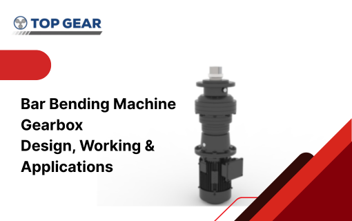
What Is a Bar Bending Machine? A bar bending machine is construction equipment used to bend steel reinforcement bars (rebar/TMT bars) into precise angles and shapes required for reinforced concrete structures. It is a standard fixture on construction sites, precast concrete yards, and rebar fabrication facilities, replacing manual bending with a mechanised process that delivers consistent bend angles, repeatable radii, and significantly higher throughput. At the heart of every bar bending machine lies its gearbox — the component responsible for converting the motor’s high-speed, low-torque output into the very high torque, low-speed rotation needed to bend thick steel bars without stalling or damaging the drive train. Role of the Gearbox in a Bar Bending Machine Torque Transmission Bending a 32 mm TMT bar requires substantial rotational force at the bending disc. The gearbox in a bar bending machine multiplies the motor’s input torque through a high reduction ratio, delivering the force needed at the bending pin without requiring an oversized, energy-inefficient motor. Speed Reduction Electric motors typically operate at 1,440–2,880 RPM, far too fast for controlled bar bending. The gearbox reduces this to a working speed of roughly 5–15 RPM at the bending disc, giving the operator precise control over bend angle and dwell time while protecting the bar from over-stress or cracking at the bend point. Planetary Gearbox Design for Bar Bending Applications Why Planetary Gearboxes Are Preferred A planetary gearbox is the preferred configuration for a bar bending machine because of its compact size relative to torque output and its ability to absorb the shock loading that occurs at the moment of bend initiation, when resistance from the bar spikes sharply. The planetary arrangement distributes this shock load across multiple planet gears rather than concentrating it on a single gear mesh, extending gearbox service life under repeated impact loading. Gear Ratio Selection Gear ratio selection for a bar bending machine gearbox depends on the maximum bar diameter the machine is rated for and the motor’s power output. Larger bar diameters (25–40 mm) require higher reduction ratios to generate adequate torque, while smaller-capacity machines (up to 16 mm) can operate with comparatively lower ratios and higher bending disc speeds for faster cycle times. Load & Duty Cycle Considerations Construction site bar bending machine gearboxes typically operate under intermittent duty with frequent direction reversal — bending, then returning to the home position. The gearbox design must handle repeated bidirectional torque reversal. This prevents backlash accumulation, which would otherwise degrade bend angle accuracy over time. Key Technical Specifications Output Torque, Speed, Power Rating Parameter Typical Specification Output Torque Several hundred to 1,000+ Nm depending on bar capacity Bending Disc Speed 5 RPM to 15 RPM Motor Power 1.5 kW to 5.5 kW (typical site-duty range) Gear Ratio High reduction (application-dependent, often 40:1 to 100:1+) Duty Type Intermittent, bidirectional, shock-loaded Mounting & Shaft Configuration Manufacturers typically foot-mount or flange-mount the bar bending machine gearbox to the base frame, directly coupling a vertical output shaft to the bending disc. This vertical orientation requires specific housing and seals to handle axial loads and prevent lubricant migration. Types of Bar Bending Machines & Matching Gearboxes Manual Bar Benders Manual or hand-operated bar benders use simple mechanical leverage rather than a powered gearbox, suitable for low-volume, small-diameter bar bending in light construction work. Electric Bar Benders Electric bar bending machine units are the standard on most construction sites, pairing an electric motor with a planetary or worm-helical gearbox sized to the machine’s rated bar capacity, typically 6 mm to 40 mm diameter. CNC Bar Bending Machines CNC bar bending machine systems integrate servo motors with precision planetary gearboxes featuring minimal backlash, enabling programmable, repeatable bend sequences for high-volume precast and rebar fabrication operations. Construction Industry Applications Reinforced concrete construction relies extensively on the bar bending machine. Teams use it for high-rise buildings, bridges, dams, and precast element fabrication. Rebar yards use higher-capacity, gearbox-driven machines for continuous, high-throughput bending. This speeds up production for the stirrups, links, and structural shapes needed in column and beam reinforcement cages. Maintenance Tips for Bar Bending Gearboxes Top Gear Transmission’s Construction Gearbox Solutions Top Gear Corporation Limited supplies planetary gearboxes and planetary geared motors for construction machinery. These solutions drive bar and pipe bending machines as part of their broader material handling range. Their modular planetary platform offers power outputs from 0.17 kW to 75 kW. It also provides torque capacities from 100 Nm to 1,000 kNm to match light-duty to heavy industrial demands. Key engineering features for bar bending applications include a high torque-to-weight ratio from modular construction. Rugged housings easily withstand harsh job site conditions. Furthermore, the platform adapts to various motor frame sizes and voltages, while individually replaceable components simplify field maintenance. Conclusion The gearbox is the engineering core of every bar bending machine, converting available motor power into the high torque, controlled-speed rotation needed to bend reinforcement steel accurately and repeatably. Planetary gearbox design, correctly matched gear ratio, and disciplined maintenance together determine how reliably a bar bending machine performs across its operational life on demanding construction sites. For construction equipment manufacturers and fabricators seeking a dependable gearbox partner, Top Gear Corporation Limited’s modular planetary gearbox range offers the torque density, shock-load tolerance, and rugged construction needed to keep bar bending and related construction machinery running reliably.
Geared Motor: Types, Working Principle & Industrial Applications
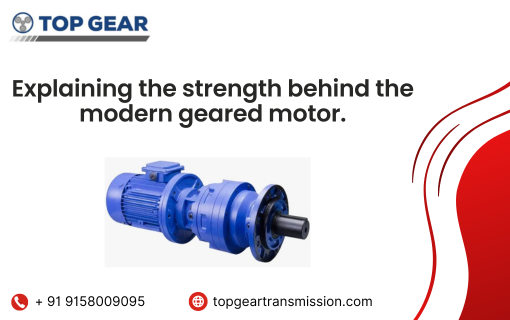
A geared motor is a self-contained drive unit that combines an electric motor with a gearbox in a single, compact assembly. This integration allows the system to deliver higher torque at reduced speeds, making it an essential component across a wide spectrum of industrial machinery and automation applications. In essence, a geared motor eliminates the need for separate motor-gearbox coupling, reducing installation complexity, footprint, and mechanical losses. Whether you are driving a conveyor belt, a robotic arm, or a mixing unit, a geared motor provides the precise speed-torque balance your application demands. The global demand for geared motors continues to rise as industries increasingly move towards automation, precision manufacturing, and energy-efficient drive systems. How Does a Geared Motor Work? Motor + Gearbox Integration A geared motor consists of two primary components: an electric motor (AC, DC, or servo) and a gearbox (or gear reducer). The motor generates rotational energy, which is then fed into the gearbox. The gearbox uses a set of meshing gear teeth arranged in specific ratios to convert the high-speed, low-torque output of the motor into a low-speed, high-torque output suitable for mechanical work. The mechanical interface between the motor shaft and gearbox input shaft ensures minimal energy loss during transmission. Modern geared motors are precision-engineered to maintain tight tolerances, reducing backlash and improving repeatability in motion control systems. Torque & Speed Relationship The fundamental principle governing a geared motor is the inverse relationship between torque and speed. When the gear ratio increases: For example, a geared motor with a 10:1 gear ratio will reduce the motor’s 1,500 RPM output to 150 RPM, while multiplying the torque approximately tenfold. This is precisely why geared motors are preferred in applications requiring controlled, powerful movement. Types of Geared Motors Planetary Geared Motor A planetary geared motor uses a central sun gear, multiple planet gears rotating around it, and an outer ring gear. This concentric design distributes load across multiple gear meshes simultaneously, resulting in: The planetary geared motor is the preferred choice for robotics, precision CNC machinery, servo-driven axes, and any application requiring accurate positioning. Its coaxial design also makes integration into tight machine layouts straightforward. Helical Geared Motor Helical geared motors use angled gear teeth that engage progressively, producing smoother and quieter operation compared to spur gears. They are well-suited for continuous-duty applications such as conveyors, compressors, and pumps, where noise reduction and smooth torque delivery are priorities. Helical geared motors are available in inline and right-angle (helical bevel) configurations. Worm Geared Motor A worm geared motor uses a worm screw meshing with a worm wheel to achieve high gear ratios in a compact package. The design inherently provides self-locking capability, making it ideal for applications such as lifts, gates, and hoists where holding a load without braking power is required. Efficiency is lower than helical variants, typically 50–90% depending on ratio. Bevel Helical Geared Motor Bevel helical geared motors combine bevel gears (for right-angle transmission) with helical stages for smooth power flow. They are widely used in heavy-duty applications including mixers, agitators, extruders, and bucket elevators where right-angle drive at high torque is required. Key Specifications to Consider When selecting a geared motor, the following parameters are critical: Industrial Applications of Geared Motors Conveyor Systems Geared motors are the workhorse of conveyor systems across logistics, food processing, automotive assembly, and packaging lines. Their ability to deliver consistent torque at controlled speeds ensures smooth material flow and reliable throughput. Mixers & Agitators In chemical processing, pharmaceuticals, and food & beverage industries, geared motors drive mixing and agitation equipment. Bevel helical and worm geared motor types are especially common here, delivering the sustained high torque required to blend viscous materials. Material Handling Cranes, hoists, and lifting platforms rely heavily on geared motors for controlled vertical movement. Self-locking worm geared motors are particularly valued in overhead cranes and stacker mechanisms for their inherent load-holding capability. Robotics & Automation The planetary eared motor dominates robotics and automation due to its compact size, high precision, and low backlash. Joint actuators in collaborative robots (cobots), pick-and-place arms, and AGVs all rely on planetary variants for their precise motion control capabilities. Geared Motor vs Standard Motor – Key Differences Parameter Geared Motor Standard Motor Output Speed Low (controlled by ratio) High (rated motor speed) Output Torque High Lower Footprint Compact (integrated) Larger (separate gearbox needed) Installation Plug-and-play Requires alignment & coupling Applications Conveyors, robots, hoists Fans, pumps, direct drives How to Select the Right Geared Motor for Your Application Choosing the correct geared motor involves a systematic approach: Working with an experienced supplier who can validate your selection calculations helps avoid costly misapplication and downtime. Top Gear Transmission’s Geared Motor Range Top Gear Transmission offers a comprehensive range of geared motors engineered for demanding industrial environments across India and global markets. The product portfolio includes: Each geared motor in the Top Gear Transmission range is manufactured to meet Indian and international standards, with options for custom gear ratios, mounting configurations, and motor specifications to suit your exact application. Conclusion A geared motor is far more than a simple drive component – it is the backbone of modern industrial automation and machinery. From the compact precision of a planetary eared motor in a robotic arm to the heavy-duty torque of a bevel helical unit driving a large mixer, the right geared motor selection makes the difference between reliable production and costly downtime. Understanding the types, working principles, and selection criteria outlined in this guide equips you to make informed decisions for your specific application. Whether you require a standard helical unit for a conveyor line or a custom planetary geared motor for a precision automation system, matching your requirements to the right product is paramount. For industry-leading geared motor solutions backed by engineering expertise and reliable after-sales support, explore the complete range from Top Gear Corporation Limited. With a proven track record across diverse industrial sectors, Top Gear Corporation Limited delivers the performance, durability, and application-specific customisation your operations demand.
High-Performance Assembly Gearbox for Modern Automation
In the modern industrial landscape, the push toward “Industry 4.0” has turned assembly lines into high-speed, hyper-precise ecosystems. At the core of this transformation is a component that often goes unnoticed until it fails: the assembly gearbox. Whether it is a robotic arm in an automotive plant or a high-speed filling line in a pharmaceutical facility, the gearbox assembly is the bridge between raw electrical power and controlled mechanical motion. This comprehensive guide explores the nuances of assembly gearboxes, their technical importance in industrial automation, and how to select the right system for peak performance. Defining the Assembly Gearbox in Automation An assembly gearbox is more than just a collection of gears; it is a sophisticated mechanical transmission system designed to modify the output of an electric motor. Its primary functions are to reduce speed and increase torque while maintaining the highest possible level of positional accuracy. In the context of industrial automation, “assembly” refers to the integrated nature of these units. Unlike standalone gears, an assembly gearbox is often pre-engineered to interface perfectly with servo motors or AC/DC motors, providing a “plug-and-play” solution for complex machinery. Why Gearboxes are Non-Negotiable Without a high-quality gearbox, a motor would have to be prohibitively large to generate the torque required to move heavy industrial loads. The gearbox allows engineers to use smaller, more efficient motors that run at higher speeds, which the gearbox then converts into the powerful, slow-moving force needed for heavy lifting or precise positioning. Key Types of Gearbox Assemblies Different automation tasks require different mechanical behaviors. Understanding the “anatomy” of these gearboxes helps in choosing the right one for your specific assembly line. A. Servo Planetary Gearboxes The “gold standard” for precision automation. In a planetary system, a central “sun” gear drives multiple “planet” gears contained within an outer “ring” gear. B. Helical Gear Assemblies Helical gears are cut at an angle to the face of the gear. This allows the teeth to engage gradually rather than all at once. C. Worm Gear Reducers Worm gears consist of a “worm” (a gear in the form of a screw) that meshes with a “worm wheel.” D. Right-Angle Gearboxes In many automation setups, space is a luxury. Right-angle gearboxes allow the motor to be mounted perpendicular to the drive shaft, saving significant floor space. The Role of Precision in Industrial Automation When we look at the specifications of a high-end assembly gearbox, two terms appear constantly: Backlash and Torsional Stiffness. Understanding Backlash Backlash is the amount of clearance between mated gear teeth. In a standard gearbox, a little backlash is fine. However, in an automated assembly gearbox, backlash must be near zero. Why? Imagine a robotic arm welding a car frame. If there is even a 0.5-degree “play” in the gearbox, the weld could be several millimeters off-target, resulting in a scrapped part. Efficiency and Thermal Management Modern gearboxes, such as those featured by industry leaders like Top Gear Corporation Limited, are designed for 95% to 98% efficiency. Higher efficiency means less energy is lost as heat. In 24/7 manufacturing environments, excessive heat can break down lubricants and lead to premature bearing failure. Critical Applications Across Industries The “assembly gearbox” is a versatile tool found in nearly every sector of the global economy: 1. Automotive Manufacturing From the stamping press to the final assembly line, gearboxes drive the heavy-duty conveyors and the precise robotic welders that build our vehicles. The high radial load capacity of planetary gearboxes makes them ideal for handling heavy car chassis. 2. Food and Beverage In this industry, gearboxes must be both precise and hygienic. Stainless steel assembly gearboxes with specialized coatings are used in bottling and packaging lines to ensure they can withstand high-pressure washdowns without rusting or leaking oil into the product. 3. Pharmaceuticals Precision is the top priority here. Gearboxes drive the machines that blister-pack pills or fill vials at speeds of thousands of units per hour. Any vibration or loss of synchronization could result in damaged medication or incorrect dosages. 4. Material Handling and Warehousing With the rise of automated warehouses (like those used by Amazon), assembly gearboxes power the automated guided vehicles (AGVs) and sorting systems that move millions of packages daily. How to Select the Perfect Assembly Gearbox Choosing a gearbox isn’t just about picking a ratio; it’s about analyzing the entire mechanical system. Here is a checklist for engineers and procurement managers: Maintenance: Ensuring Longevity Even the best-engineered assembly gearbox requires care. To avoid unplanned downtime, follow these three pillars of maintenance: The Future: Smart Gearboxes and Industry 4.0 The next generation of assembly gearboxes is getting “smart.” We are now seeing the integration of IoT sensors directly into the gearbox housing. These sensors monitor temperature, torque, and vibration in real-time, sending data to the cloud. This allows for Predictive Maintenance, where the machine itself tells the operator, “I need a part replaced in 200 hours,” rather than waiting for a catastrophic breakdown. Conclusion: Driving the Future of Production The assembly gearbox is the silent workhorse of the industrial world. As automation becomes more complex, the demands on these mechanical systems will only increase. By selecting high-quality, high-precision gearboxes, manufacturers can ensure their operations are faster, more accurate, and more cost-effective. When you invest in a superior gearbox assembly, you aren’t just buying hardware you are buying the reliability and precision that keeps your production line moving toward the future.
Shaft Mounted Gearbox: Uses, Benefits & Buying Guide
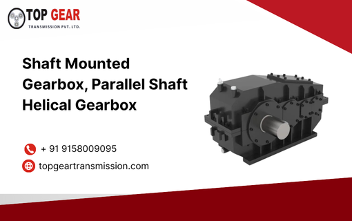
Operational efficiency and reliability are among the cornerstones of modern industrial operations. However, no manufacturer inherits them. Each one must earn it. In today’s highly competitive world, accomplishing these goals isn’t possible with archaic systems and equipment. You need an innovative solution. This is where shaft mounted gearboxes come into play. Lately, they’ve emerged as the top choice for every manufacturing company that handles heavy-duty machines. Thanks to their simplicity, durability, and high performance. But what exactly is a shaft mounted gearbox? What are its applications, and how can you benefit from them? Here’s a blog that breaks down these aspects to serve as a buying guide. What is a Shafted Mounted Gearbox? A shafted mounted gearbox is an industrial speed reducer installed onto the driven shaft of a machine. Therefore, it eliminates the need for a complex base mounting or making coupling arrangements. The gearbox is commonly used in systems where space-saving, minimal maintenance, and ease of mounting are crucial factors. Furthermore, since the gearbox shifts on the shaft, it reduces misalignment issues and helps enhance the overall system reliability. Working Principle and Design The main purpose of a shafted mounted gearbox is to reduce input speed, while increasing torque output. Here’s how it functions. Some key design features of these gearboxes include: Let us now look at some of the types of gearboxes. Types of Shafted Mounted Gearboxes Top-tier industrial gearbox manufacturers manufacture a wide range of shafted mounted gearboxes. Two popular choices include: This gearbox features parallel input and output shafts. Hence, it is used in applications that require high torque, consistent performance, and continuous duty operations. The gearbox has a compact design and high load-carrying capacity. Such a gearbox uses helical gears. They are angled tooth gears that operate more smoothly and quietly than spur gears. The gearbox also delivers higher efficiency, ensures better load distribution, and provides a longer service life. Hence, industrial operations that require precision and durability prefer this type of gearbox. Advantages of Shafted Mounted Gearboxes From high efficiency to ease of installation and low maintenance, here’s why shafted mounted gearboxes are among the premier choices of modern industrial operations. The above benefits make shafted mounted gearboxes integral to various applications. Let us look at some of them in the next section. Applications of Shafted Mounted Gearboxes Shafted mounted gearboxes aren’t just efficient and durable but also versatile. Hence, they have widespread applications across the industrial world, including: How to Choose the Right Gearbox Company in India Selecting the right gearbox company in India is crucial from the viewpoint of performance, durability, quality, and maintenance. So, here are some factors to consider while choosing industrial gearbox manufacturers. Final Words In a world where efficiency and power matter, shafted mounted gearboxes play a crucial role. Besides, they are easy to install, durable, and deliver superior performance. So, if you are from the material handling, mining, or food processing industry and looking for shaft mounted gearbox systems, Top Gear Transmission has got you covered. We are one of the top industrial gearbox manufacturers with a broad product range, market credibility, experience, client trust, and a reputation for quality. Explore our product range and connect with us at sales@topgeartransmission.com to discuss your requirements with our product specialists.
Why Cycloidal Gearboxes Are Ideal for High Torque Applications
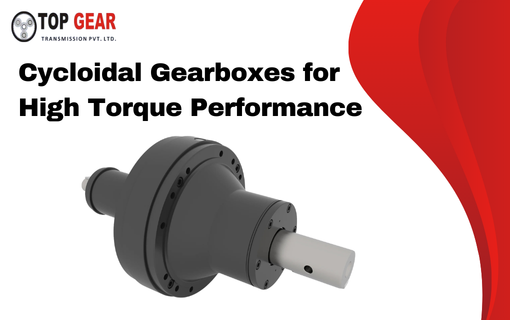
In the industry of today, there is a need to attain high levels of output in terms of torque reliability, and efficiency. Industries such as robotics, automation, heavy machinery, and material handling require reliable power transmission systems. These systems must handle heavy loads without compromising precision. Among other technologies that have proven to be unique in these challenging applications is the Cycloidal Gearboxes system. Cycloidal gear mechanisms have a reputation of being exceptional in terms of torque capacity, compact in nature and enduring. They are very popular in the industrial arena where they are extensively employed in high-tech activities. Such firms as Top Gear Transmission are offering the quality cycloidal gears solutions which are effective in rendering optimum performance in the harsh environment. Understanding Cycloidal Gearboxes Cycloidal Gearboxes are known to work on a different mechanism that is quite different to the traditional gear system. A cycloidal gearbox involves an eccentric shaft and discs of cycloidal teeth which roll against pins within the housing instead of the normal engagement of traditional gear teeth. This motion reduces speed and multiplies torque efficiently. The system distributes the load across multiple contact points at the same time. This design allows the gearbox to handle much higher torque than traditional gear systems. This new mechanism is the guarantee of the smoothing of operation, high efficiency, and extended service. High Torque Density in Compact Design High torque density is one of the main reasons industries choose Cycloidal Gearboxes for demanding applications. Torque density refers to the amount of torque a gearbox can deliver compared to its size. The unique design of cycloidal gear mechanisms allows multiple lobes or contact points to share the load at the same time. This design improves load distribution and increases torque capacity.This distributes the pressure evenly through the system and enables the gearbox to be able to transmit more torque without the need to be larger. This small high power design can be of great value to industries that do not have much space but need a lot of power. Exceptional Shock Load Resistance Impulse loads or impacting forces are typical in heavy service industrial work. Traditional gear systems may fail when they face extreme shock or heavy load conditions. However, cycloidal gear systems handle high shock loads more effectively. Their design spreads the load across multiple contact points instead of a few gear teeth. This structure allows the system to absorb sudden forces more efficiently. There are situations when these gearboxes can withstand shock loads that are more than the specified torque carrying capacity. This makes them suitable for demanding equipment such as cranes, conveyors, robotic systems, and heavy industrial machinery. Minimal Backlash and High Precision Backlash refers to the slight movement between gear teeth when the direction of motion changes. Too much backlash may cause a lack of accuracy and efficiency in mechanical systems. The cycloidal gear designs have a large contact ratio with a high precision engineering and thus a high reduction of backlash. The outcome of this is very precise motion control and positioning. This precision is particularly vital in tasks such as robotics, CNC machines, and automated production systems where a few centimeters of positioning mistakes can have a significant impact. Improved Efficiency and Long Service Life One more benefit of cycloidal gear systems is that they are highly efficient and durable. Friction and wear are minimised by the rolling movement of components as opposed to the traditional sliding gear mechanisms. Due to this design, Cycloidal Gearboxes are smooth in operation, need low maintenance and have extended life. There are also models that achieve efficiency of above 90 percent and hence are efficient in terms of energy consumption in industrial operations. These gearboxes can be used with many years of maintenance under the conditions of constant heavy load. Versatile Industrial Applications Due to their durability and torque capacity, cycloidal gear systems are used in a wide range of industries, including: The combination of compact size, high reduction ratios, and reliable performance makes them suitable for both precision and heavy-load applications. High-Performance Solutions from Top Gear Transmission When selecting a gearbox for high torque applications, reliability and quality become critical factors. Top Gear Transmission offers high-performance cycloidal gearboxes designed to meet the demanding needs of modern industries. The company engineers these gearboxes with precision components, high torsional rigidity, and low backlash. This design ensures efficient operation and accurate performance. These gear systems offer high transmission ratios even in compact sizes. They are designed for durability and reliable performance. Their design also helps reduce maintenance requirements. Top Gear Transmission has strong engineering expertise and extensive industry experience. The company continues to deliver reliable power transmission solutions. These solutions support automation, manufacturing, and heavy machinery industries. Conclusion Gears used in high torque operations must be robust, accurate and reliable. One of the most effective solutions to such a demanding environment has been the technology of cycloidal gear. Its benefits such as high torque density, shock loads resistance, compactness, and low backlash can make one easily understand why Cycloidal Gearboxes have found extensive application in various sectors. The use of reputable manufacturers such as Top Gear Transmission will enable businesses to obtain long-lasting and high-performance gear solutions that can maintain the operations of the modern industries.
Common Gearbox Problems and How to Solve Them
Industrial gearboxes are critical components in the operation of manufacturing units, automation systems, material handling, and energy production. Despite their robust design, gearboxes can encounter performance issues due to environmental, operational, or maintenance-related factors. In this guide, India’s trusted gearbox manufacturing company, Top Gear Transmission, explores the most common gearbox problems and how to effectively resolve them. Common Industrial Gearbox Problems, Types & Their Causes Now, let’s explore the common problems that can occur in these gearboxes and how to solve them: 1. Overheating Symptoms: High casing temperature, unusual smell, reduced efficiencyCauses: Solution: 2. Excessive Noise or Vibration Symptoms: Humming, knocking, or grinding noise during operationCauses: Solution: 3. Lubrication Leaks Symptoms: Oil stains, low lubricant levels, overheatingCauses: Solution: 4. Gear Wear or Scoring Symptoms: Metal particles in oil, loud operation, drop in torqueCauses: Solution: 5. Misalignment Issues Symptoms: Coupling failure, shaft wear, vibrationCauses: Solution: Preventive Maintenance Tips Why Choose Top Gear Transmission? As a trusted gearbox company in India, Top Gear Transmission is known for: Main types of industrial gearboxes: FAQs Q1: How often should industrial gearboxes be serviced? A: Typically every 3–6 months depending on operating conditions. Q2: What type of gearbox is best for heavy loads? A: Planetary and helical gearboxes are ideal due to their high torque capacity and load distribution. Q3: How do I know if my gearbox is failing? A: Signs include noise, overheating, oil leakage, and reduced performance.
How to Choose the Right Gearbox for Your Application

Lorem Ipsum is simply dummy text of the printing and typesetting industry. Lorem Ipsum has been the industry’s standard dummy text ever since the 1500s, when an unknown printer took a galley of type and scrambled it to make a type specimen book. It has survived not only five centuries, but also the leap into electronic typesetting, remaining essentially unchanged. It was popularised in the 1960s with the release of Letraset sheets containing Lorem Ipsum passages, and more recently with desktop publishing software like Aldus PageMaker including versions of Lorem Ipsum. FAQs What factors should I consider when selecting a gearbox for my application? When choosing a gearbox, consider factors such as load capacity, torque requirements, speed range, environmental conditions, and the type of application. Understanding these parameters helps in selecting a gearbox that meets your specific needs and ensures optimal performance. How do I determine the right gearbox size for my application? To determine the right gearbox size, calculate the input power and output torque required for your application. It’s essential to consider the gear ratio and the efficiency of the gearbox to ensure it can handle the operational demands effectively. What are the different types of gearboxes available for industrial applications? Common types of gearboxes include helical, bevel, worm, and planetary gearboxes. Each type offers unique benefits; for instance, planetary gearboxes provide high torque in a compact design, while helical gearboxes offer smooth operation and high efficiency. How can I ensure my chosen gearbox is suitable for high-speed applications? For high-speed applications, select a gearbox designed specifically for such conditions, paying attention to gear materials, lubrication, and cooling systems. Reviewing the manufacturer’s specifications and performance data can also help ensure the gearbox can handle the required speed. Should I consider gearbox maintenance requirements when choosing a gearbox? Yes, considering maintenance requirements is crucial when selecting a gearbox. Look for gearboxes that offer easy access for maintenance, and review the recommended service intervals. Proper maintenance can significantly enhance the lifespan and reliability of the gearbox in your application.
Understanding Types of Gearbox: A Comprehensive Guide

What is a Gearbox? A gearbox is a mechanical system that transmits power from a motor to a machine, adjusting the torque and speed through gear reduction or multiplication. It plays a crucial role in optimizing performance, especially in industrial equipment, by matching power output with operational requirements. Types of Gearbox and Their Applications Explore the most common gearbox types used across industries, along with their working principles, benefits, and ideal use cases. There are generally 6 main types of gearboxes commonly used across industrial and mechanical applications. 1. Helical Gearbox How It Works: Uses angled teeth that engage gradually, providing smooth and quiet operation. Applications: Advantages: 2. Planetary Gearbox How It Works: Features a central sun gear, rotating planet gears, and an outer ring gear. Distributes load evenly for high torque in a compact design. Applications: Advantages: 3. Worm Gearbox How It Works: A worm screw engages with a worm wheel to reduce speed and transmit motion at 90 degrees. Applications: Advantages: 4. Bevel Gearbox How It Works: Uses bevel gears to change rotational direction, typically at a 90-degree angle. Applications: Advantages: 5. Spur Gearbox How It Works: Straight-cut teeth mounted on parallel shafts. Basic and cost-effective. Applications: Advantages: 6. Cycloidal Gearbox How It Works: Replaces traditional gears with a cycloidal disc and rollers, enhancing torque and precision. Applications: Advantages: How to Select the Right Gearbox When choosing a gearbox, consider the following: Conclusion Different gearbox types serve distinct purposes. Choosing the right one can boost efficiency, reduce downtime, and extend equipment life. At Top Gear Transmission, we provide expert support to match the ideal gearbox with your specific application. FAQs Q1: What is the most efficient gearbox type? Planetary gearboxes are among the most efficient, with up to 97% efficiency. Q2: Can gearboxes be customized for specific needs? Yes, at Top Gear Transmission, we offer custom designs based on torque, mounting, and operational requirements. Q3: What industries use gearboxes the most? Gearboxes are widely used in robotics, packaging, agriculture, construction, and renewable energy sectors.